

In this venture, I created a unique exposure box designed for photolithography-based PCB manufacturing. The exposure light stems from a 20W LED floodlight, originally designed for outdoor use, but its slim profile makes it an excellent choice for my exposure box. The electronic components run on an existing power supply that provides a steady 12V and 1.2A.
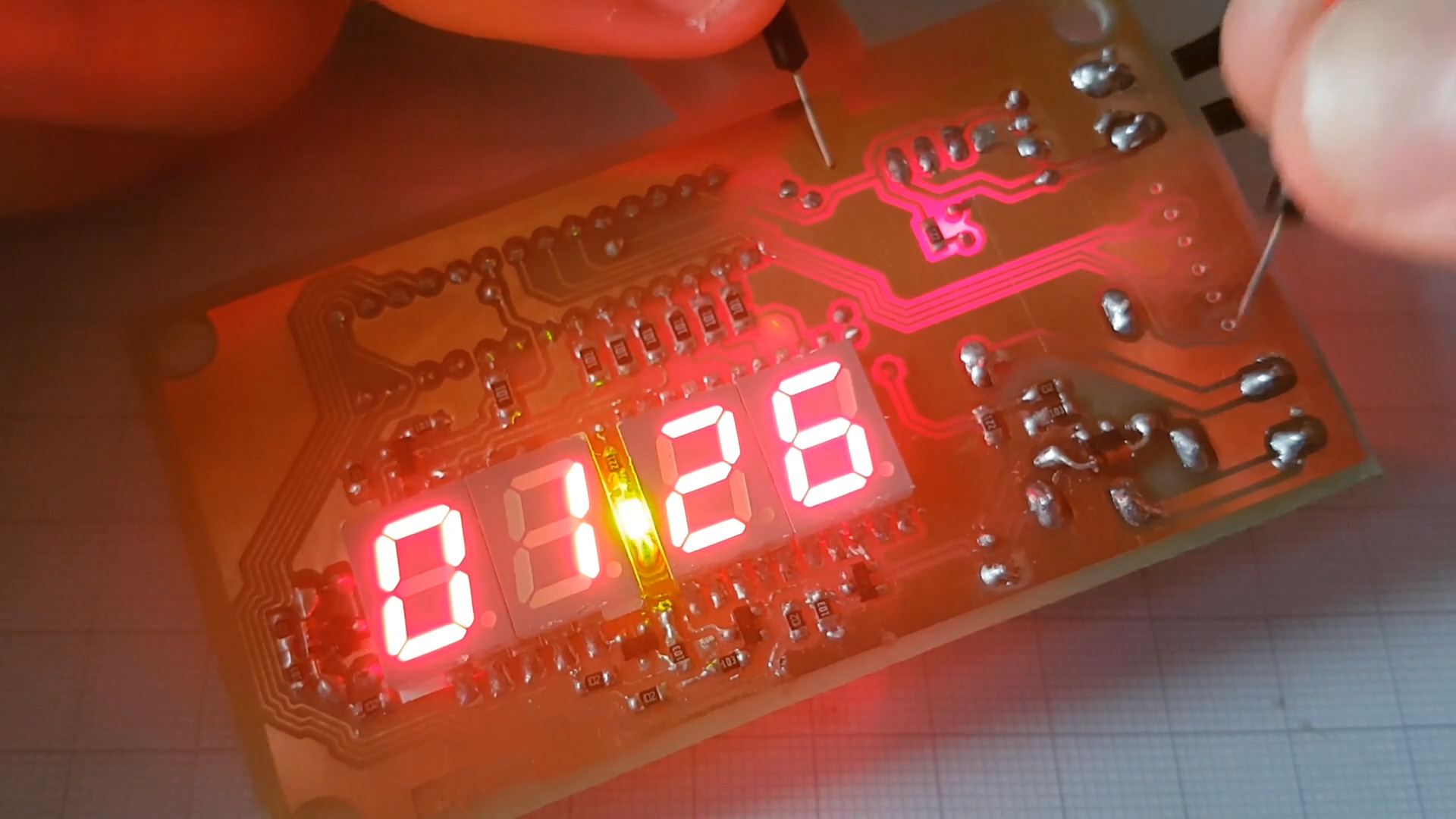
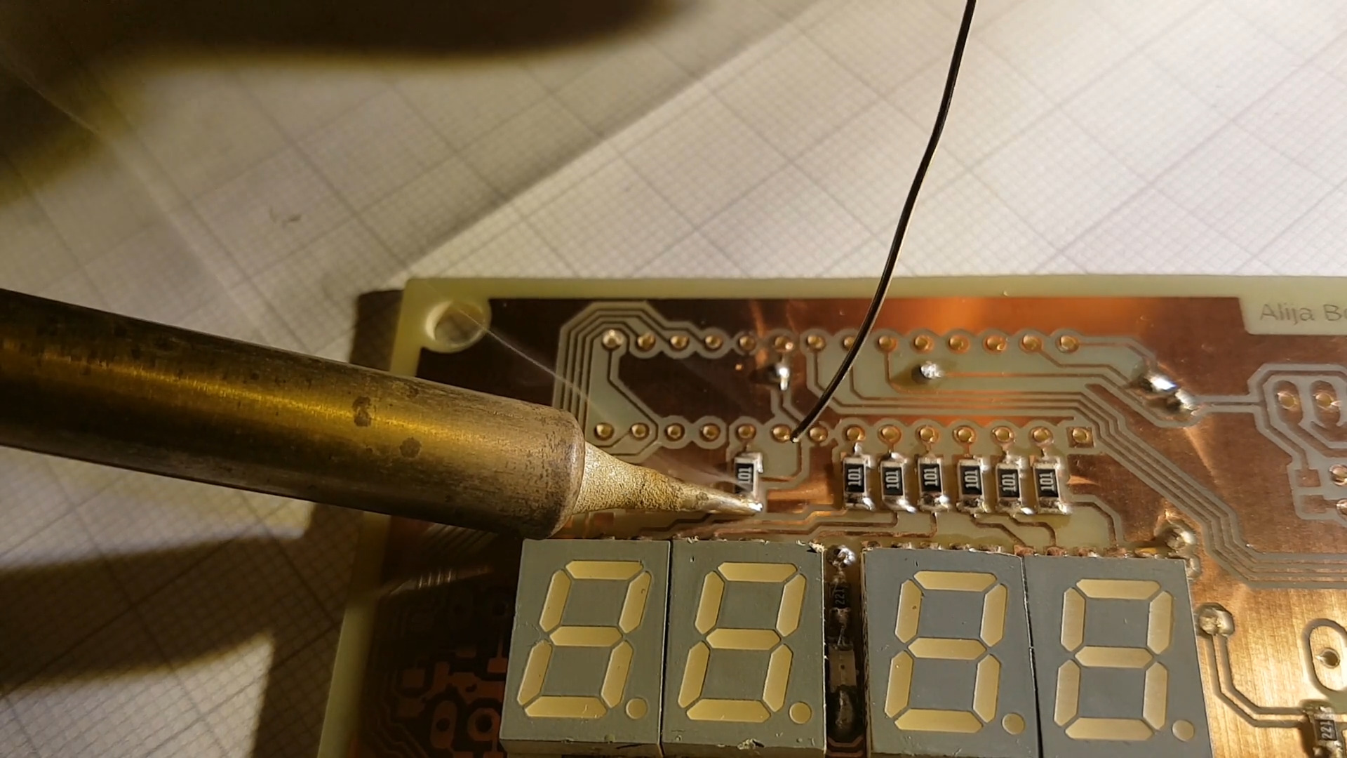
The heart of this exposure box is the PIC16F886 microcontroller. Display segments are connected to port A, while multiplexing is accomplished by pins 4, 5, 6, and 7 of port C. Each display can be illuminated via low power NPN transistor switches. The buttons are linked to the first three pins of port B, making use of the MCU’s internal weak pull-up resistors which can be controlled programmatically.
What’s more, I’ve configured the microcontroller to trigger an interrupt upon any detected changes on this port. The piezo speaker on pin RC2 is driven by a PWM signal routed through an NPN transistor. An LED for pulsing, on port RB7, and a relay for the exposure light, on port RB6, come into action when the pin level rises. A reliable 7805 regulator ensures a steady output of 5V for the entire circuit.
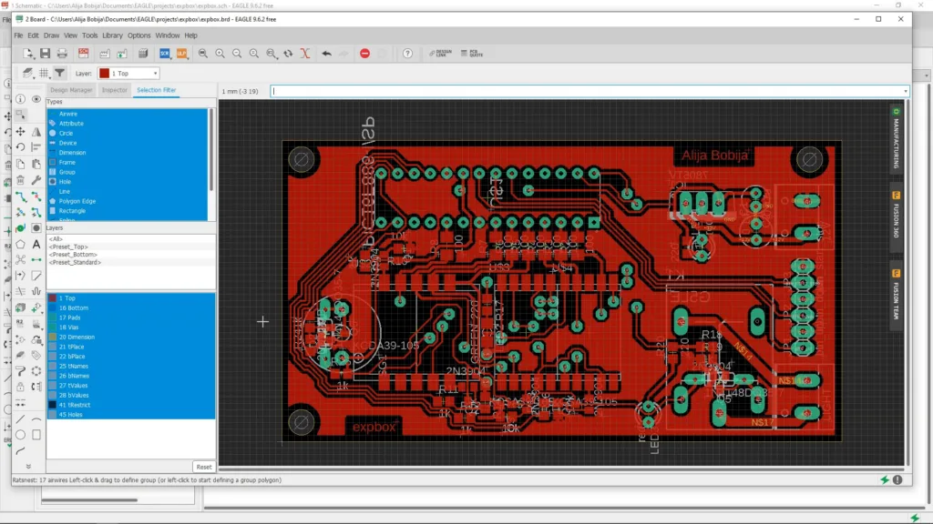
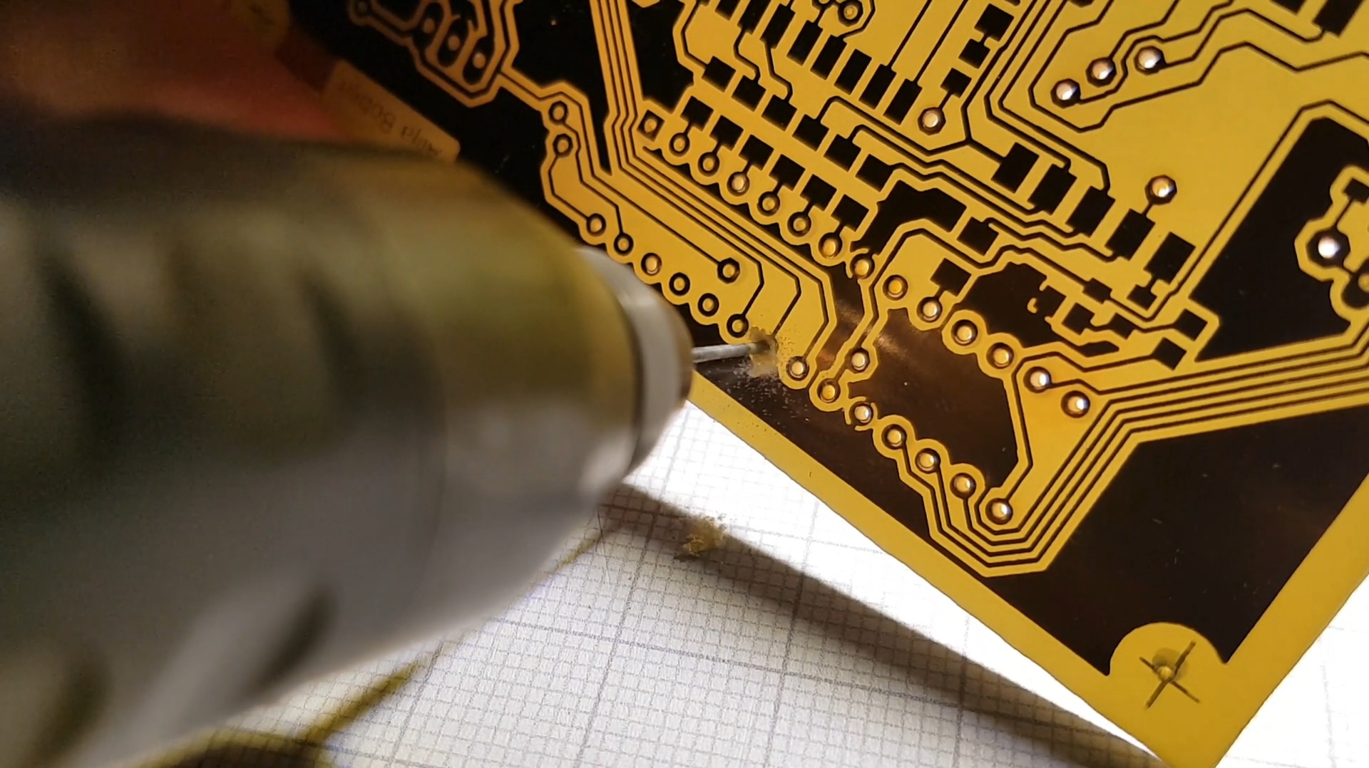
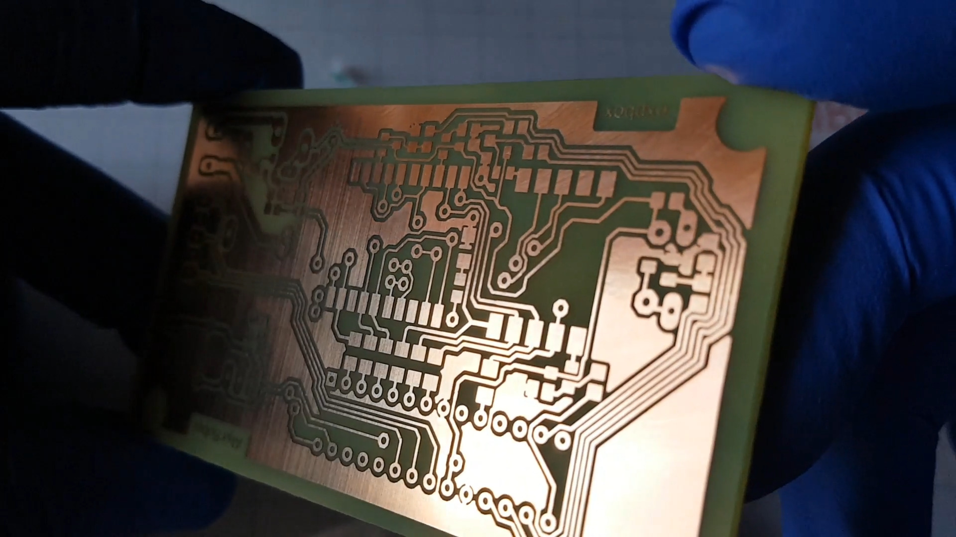
The PCB dimensions are 87 by 47 millimeters, a one-sided PCB entirely designed on the top layer. Despite its compact size, it hosts a variety of components, thanks to innovative small SMD displays and other predominantly SMD type components.
To house the PCB, exposure light, power supply, and other components, I designed an internal box using Sketchup that ensures the PCB stays above the exposure light. This box, along with the entire setup, is nestled within a larger plastic container.
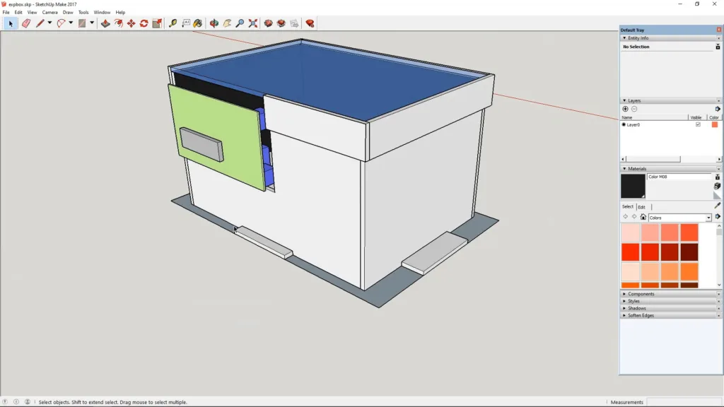
The project yields an efficient exposure box, with a glass dimension of 12 by 17 centimeters that lays directly on the box walls. I created the internal box from 3mm thick cardboard, giving the project a homemade feel while retaining its professional functionality.


The final product, while fit for my personal needs, represents a labor of love and learning. Despite the initial video quality, the exposure box performs perfectly, with the 20W LED floodlight ensuring a complete exposure in 12-15 minutes.
Software
For the tech enthusiasts out there, the software for the PIC microcontroller is completely written in C, and I used the mikroC IDE from Mikroelektronika. The code, which employs internal PIC timers for display multiplexing and button debouncing, is available as open-source on my GitHub profile. It’s an interesting approach, and I encourage you to check out the code.
GitHub Repository
Summary
In summary, this project was not only about creating a practical tool for my PCB design needs, but also a journey of learning and enhancing my skills in PIC microcontrollers and PCB design.